新闻资讯
NEWS

Detailed Explanation of Ultra-High Molecular Weight Polyethylene Processing Technology
Ultra-High Molecular Weight Polyethylene Processing Technology
Abstract: Ultra-high molecular weight polyethylene, abbreviated as UHMW-PE, is a type of thermoplastic engineering plastic that is abundant in source, moderately priced, and excellent in performance. Due to its impact resistance, corrosion resistance, wear resistance, self-lubricating properties, non-toxicity, and excellent low-temperature resistance, it is used in many fields. "Excellent performance but difficult to process" is a major characteristic of UHMW-PE. The reason lies in the extremely long molecular chain of UHMW-PE, which causes the molecular chains to become entangled with each other, making it difficult to arrange them regularly. While causing changes in aggregation state (such as low crystallinity -65%~85%, low density -0.93~0.94g/m3), the irregular entanglement of macromolecular chains also makes UHMW-PE slow to respond to thermal motion. When heated above the melting point, the melt exhibits a rubber-like highly viscoelastic state, with a melt viscosity of up to 108 Pa.s and a melt flow rate of almost zero. This results in a very low critical shear rate for UHMW-PE, which can easily lead to defects such as melt fracture. Therefore, it is difficult to use conventional polymer processing methods to mold UHMW-PE products, which has limited the promotion and use of UHMW-PE for some time. Thus, studying the molding process of UHMW-PE is particularly important. The commonly used molding methods include compression molding (around 1965), extrusion molding (around 1970), and injection molding (around 1975). This paper first briefly introduces the performance and molding methods of UHMW-PE, and then provides a detailed introduction to its single-screw extrusion molding process and twin-screw extrusion molding process.
Keywords: performance; processability; molding methods; single-screw extrusion molding; twin-screw extrusion molding
1. Overview of UHMW-PE
1.1 Brief History of UHMW-PE Development
Ultra-high molecular weight polyethylene (UHMW-PE) typically refers to linear polyethylene with a relative molecular mass of over 1.5 million. UHMW-PE shares the same molecular structure as regular polyethylene, with the main chain consisting of (-CH2-CH2-) links. However, regular polyethylene has a lower molecular weight, ranging from 50,000 to 300,000. Even high molecular weight high-density polyethylene (HMWHPE) has a weight average molecular weight of only 200,000 to 500,000, whereas UHMW-PE can reach up to 6 million or even higher. In Germany, products with a molecular weight exceeding 10 million are available.
UHMW-PE is a thermoplastic engineering plastic known for its abundance, moderate price, and excellent performance. Its impact resistance, corrosion resistance, wear resistance, self-lubricating properties, non-toxicity, and exceptional low-temperature resistance make it widely used in various fields like general machinery, chemical machinery, food processing, and papermaking. UHMW-PE is commonly applied in components and parts that are prone to wear, corrosion, high impact, and low temperatures, as well as in applications where lubricants cannot be used, such as silo liners, chutes, slide plates, slide rails, and fuel tanks. The service life of UHMW-PE materials surpasses that of nylon and polytetrafluoroethylene products, and its wear resistance far exceeds that of metal products like stainless steel. Due to its comprehensive performance, UHMW-PE is known as the "amazing plastic"[1] overseas.
UHMW-PE was first developed successfully by Hoechest of West Germany in 1958, followed by large-scale industrial production by Hercules in the United States and Mitsui Oil Chemicals in Japan. Beijing Auxiliary Agent Plant No. 2 is a major domestic manufacturer of UHMW-PE in China. For a long time, the promotion and application of UHMW-PE materials were somewhat limited due to processing difficulties. However, recent advancements and developments in processing technology have expanded its application areas. Currently, the processing of UHMW-PE products still mainly relies on press sintering and plunger methods. Since the mid-1970s, Japan has developed single-screw extrusion and reciprocating screw injection molding processes, while the United States and West Germany have also adopted single-screw extrusion and injection molding methods to process UHMW-PE products.
1.2 Synthesis Methods of UHMW-PE
The synthesis method of ultra-high molecular weight polyethylene is similar to that of regular high-density polyethylene. Mostly, Ziegler catalysts are used to polymerize polyethylene under certain conditions, yielding ultra-high molecular weight polyethylene. Additionally, there are also the Solvay process and the U.C.C. gas-phase method.
(l) Ziegler Low-Pressure Slurry Method
Using β-TiCl3/Al(C2H5)2Cl or TiCl4/Al(C2H2)2Cl as the catalyst and saturated hydrocarbons from the 60~120℃ fraction as the dispersing medium (or heptane, gasoline as solvents), polyethylene is polymerized at atmospheric or near-atmospheric pressure and a temperature of 75~85℃. This process synthesizes ultra-high molecular weight polyethylene with a relative molecular mass ranging from 1 to 5 million.
(2) Solvay Process
In the Solvay process, the catalyst uses magnesium oxide as a carrier and organometallic compounds as catalysts. By varying the activation temperature of the carrier, the relative molecular weight of the polymer can be adjusted. The production process involves adding ethylene, comonomer, catalyst, hydrogen, and hexane (diluent) together into a loop reactor. The reaction temperature is maintained at 60~90℃, the reaction pressure is 3MPa, the residence time is 2.5~3.0h, the slurry concentration in the reactor is 28%, and the ethylene conversion rate can reach 85%-93%. The polymer slurry undergoes double stripping, centrifugation, drying, and pelletizing to obtain the finished product.
(3) U.C.C. Gas-Phase Method
The U.C.C. gas-phase method, invented by Union Carbide Corporation, directly produces dry polyethylene powder through gas-phase low-pressure polymerization of ethylene in a fluidized bed. Organic chromium compounds or Ziegler catalysts, with silica gel as the carrier, are commonly used as catalysts. The polymerization reaction occurs in a fluidized bed reactor at a temperature of 95~105℃, a pressure of 2.1MPa, and a residence time of 3~5h.
1.3 Properties of UHMW-PE
UHMW-PE's extremely high molecular weight (the molecular weight of HDPE is usually only 20,000 to 300,000) gives it excellent performance, and it is a thermoplastic engineering plastic with moderate price and excellent performance. It almost centralizes the advantages of various plastics, with unparalleled wear resistance, impact resistance, self-lubrication, corrosion resistance, impact energy absorption, low-temperature resistance, hygiene and non-toxicity, non-adhesion, low water absorption, and low density compared to ordinary polyethylene and other engineering plastics. In fact, there is currently no single polymer material that possesses such a wide range of excellent properties [3].
1.3.1 Wear Resistance
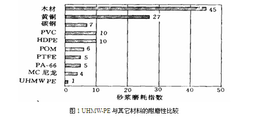
UHMW-PE tops the list of plastics in wear resistance, even surpassing some metals. Figure 1 compares the wear resistance of UHMW-PE with other materials. As seen in Figure 1, compared to other engineering plastics, UHMW-PE's slurry wear index is only 1/5 of PA66 and 1/10 of HDPE and PVC; compared to metals, it is 1/7 of carbon steel and 1/27 of brass. Its wear resistance is so high that it is difficult to test its wear degree using the general plastic wear test method, so a special slurry wear test device has been designed. The wear resistance of UHMW-PE is proportional to its molecular weight; the higher the molecular weight, the better its wear resistance.
Figure 1 Comparison of wear resistance between UHMW-PE and other materials
1.3.2 Impact Strength
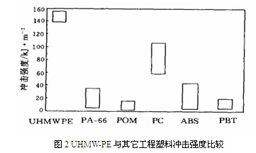
UHMW-PE's impact strength ranks among the top engineering plastics. Figure 2 compares the impact strength of UHMW-PE with other engineering plastics. As shown in Figure 2, the impact strength of UHMW-PE is approximately twice that of impact-resistant PC, five times that of ABS, and more than ten times that of POM and PBTP. Its impact resistance is so high that it is difficult to cause fracture damage using conventional impact testing methods. The impact strength increases with molecular weight, reaching a maximum at a molecular weight of 1.5 million, and then gradually decreases as the molecular weight continues to increase. It's worth noting that it can maintain excellent impact strength even in liquid nitrogen (-196℃), a feature not found in other plastics. Additionally, its surface hardness increases after repeated impacts.
1.3.3 Self-lubricating Properties
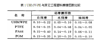
UHMW-PE has a very low friction coefficient (0.05~0.11), resulting in excellent self-lubricating properties. Table 1 compares the friction coefficients of UHMW-PE with other engineering plastics. As seen in Table 1, the dynamic friction coefficient of UHMW-PE is half that of PA66 and POM under water-lubricated conditions and is second only to polytetrafluoroethylene (PTFE), the best self-lubricating plastic, under unlubricated conditions. When it works in sliding or rotating form, it provides better lubrication than steel and brass with added lubricating oil. Therefore, in the field of tribology, UHMW-PE is known as a very cost-effective friction material.
1.3.4 Chemical Resistance
UHMW-PE exhibits excellent chemical resistance. Apart from strongly oxidizing acids, it can withstand various corrosive media (acids, alkalis, salts) and organic solvents (except naphthalene solvents) within a certain temperature and concentration range. After being immersed in 80 organic solvents at 20℃ and 80℃ for 30 days, its appearance remained unchanged, and there were almost no changes in its other physical properties.
1.3.5 Impact Energy Absorption
UHMW-PE has excellent impact energy absorption, with the highest impact energy absorption value among all plastics. This results in good noise damping properties and excellent soundproofing effects.
1.3.6 Low-temperature Resistance
UHMW-PE demonstrates superior low-temperature resistance, remaining ductile even at liquid helium temperature (-269℃), making it suitable for use as a low-temperature resistant component in the nuclear industry.
1.3.7 Hygiene and Non-toxicity
UHMW-PE is hygienic and non-toxic, fully complying with the standards of the Japan Hygiene Association. It has also been approved by the US Food and Drug Administration and the US Department of Agriculture for contact with food and drugs.
1.3.8 Non-stick Properties
The surface adhesion of UHMW-PE is very weak, and its anti-adhesion ability is second only to PTFE, the best non-stick plastic. Therefore, the surface of the product is not easy to adhere to other materials.
1.3.9 Hydrophobicity
UHMWPE has a very low water absorption rate, generally less than 0.01%, which is only 1% of PA6. Therefore, drying treatment is generally not necessary before molding processing.
1.3.10 Density
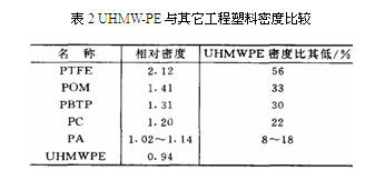
Table 2 compares the density of UHMW-PE with other engineering plastics. As shown in Table 2, UHMW-PE has a lower density than all other engineering plastics, generally 56% lower than PTFE, 33% lower than POM, and 30% lower than PBTP, making its products very lightweight.
1.3.11 Tensile Strength
UHMW-PE possesses unparalleled ultra-high tensile strength due to its structural characteristics necessary for ultra-drawing orientation. Therefore, fibers with ultra-high elastic modulus and strength can be produced through the gel spinning method. These fibers have a tensile strength of up to 3-3.5 GPa and a tensile elastic modulus of 100-125 GPa. The specific strength of these fibers is the highest among all commercialized fibers to date, being 4 times greater than carbon fiber, 10 times greater than steel wire, and 50% larger than aramid fiber.
1.3.12 Other Properties
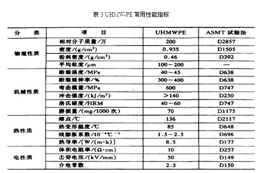
UHMW-PE also exhibits excellent electrical insulating properties, better environmental stress cracking resistance than HDPE, and superior fatigue resistance and gamma ray resistance compared to HDPE. Table 3 presents the common performance indicators of UHMW-PE [4].
1.4 Application Fields of UHMW-PE
(1) Textile Machinery: Ultra-high molecular weight polyethylene has been used in textile machinery since its early stages. As early as 1958, when it first appeared, it was applied to various components such as picker sticks, shuttle boards, gears, buffer blocks, bushings, connectors, and more, with over 30 different products.
(2) Construction, Electricity, and Agricultural Machinery: Applications include lining plates for bulldozer blades, excavator bucket liners, coal bunker liners in power plants, tractor plow liners, and bushings.
(3) Paper Industry: The paper industry is one of the sectors where ultra-high molecular weight polyethylene is widely used and highly effective. Its applications include suction box covers and squeegees for paper machines.
(4) Ceramic Industry: Mainly used in rolling heads, filter plates, and filter elements.
(5) Mining Industry: Applications include coal bunker liners, coal chute plates, lifting tracks, rollers, filter press plates, conveyor belt rollers, and roller bearings.
(6) Food Machinery: Food molds, feeding screws, various guide rails, gears, rollers, and cutting boards for food and meat.
(7) Military Field: Such as bulletproof vests and target shields.
(8) Medical, Cultural, and Sports Fields: Applications include artificial joints, sledges, skating rink floors, sandboarding bottoms, and protective plates for ships at docks.
2. Introduction to the Processing Technology of UHMW-PE
2.4 Processing Performance of UHMW-PE
When adopting common thermoplastic processing methods to mold UHMW-PE, four main difficulties are encountered:
(l) High Melt Viscosity
The melt of ultra-high molecular weight polyethylene is a rubbery, highly viscoelastic body. The flow performance of ordinary polyethylene is generally represented by the melt flow rate (MFR), which is measured at a temperature of 190°C under a load of 2.16kg. The melt flow rate of common thermoplastic melts ranges from 0.03 to 30g/10min. However, due to the extremely high melt viscosity of ultra-high molecular weight polyethylene, results cannot be measured under the aforementioned conditions. Even if the load is increased by 10 times (i.e., 21.6kg), the melt is difficult to flow out of the instrument nozzle. This illustrates the poor fluidity of ultra-high molecular weight polyethylene during processing[5].
When ordinary polyethylene is processed in an extruder, the solid pellets or powder added from the hopper gradually transform into a viscous fluid under the heat of the barrel and the shearing action of the screw. Even if the screw design and temperature conditions are not ideal, it will not cause the material to get stuck in the barrel or completely fail to extrude. However, the situation is completely different when extruding UHMW-PE. The movement of the material throughout the screw is similar to a solid conveying process, namely, a "powder-semi-solid-highly viscoelastic body" transformation process. This is a typical "plug flow" conveying mechanism without a free-flowing viscous state. The material is prone to getting stuck in the compression section, wrapping around the screw, and rotating without being able to extrude. This phenomenon is also known as "material plugging." This is the biggest challenge encountered when using an ordinary, unmodified single-screw extruder to process UHMW-PE.
Experimental research indicates that ordinary polyethylene melts in a viscous fluid state and immediately sags after being extruded from the die (as shown in Figure 3). In contrast, molten UHMW-PE exhibits a certain "melt stiffness" when extruded from a high-temperature die, and does not sag immediately. Instead, it moves horizontally and slightly downwards in a translucent solid state, demonstrating a highly viscoelastic behavior (as shown in Figure 4). This suggests that UHMW-PE, when molten, is a special type of melt with extremely high viscosity and poor fluidity.
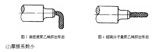
(2) Low Friction Coefficient
UHMW-PE has a very low friction coefficient, even in its molten state. As a result, it is prone to slipping in the feeding section during the feeding process, making it difficult to advance. This poses another challenge in screw extrusion processing.
(3) Low Critical Shear Rate
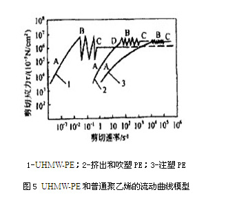
Figure 5 illustrates the flow curve of ultra-high molecular weight polyethylene [6]. Generally, during extrusion, the shear rate for extruding rods, ordinary products, and monofilaments ranges from 10-3 to 104 s-1. The shear rate for blow molding is 104 s-1, while the shear rate for injection molding is between 102 and 106 s-1. Typically, the larger the cross-sectional area of the product, the lower the extrusion volume per unit time and the shear rate.
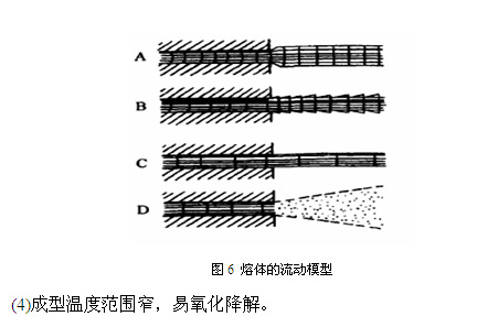
As shown in Figure 3, the flow curves of UHMW-PE and ordinary polyethylene used for injection molding, extrusion, and blow molding can be divided into four states [7], as illustrated in Figure 6: A represents laminar flow, where material flows within the die at low speeds, resulting in die swell at the exit of the die; B denotes melt fracture flow, where the extruded material appears rough and sharkskin-like; C is plug flow, where the melt is not subjected to shear, and there is no relative displacement between the layers of the melt. However, unlike laminar flow, it does not produce die swell; D signifies jet flow, where the melt is sheared into a powder-like spray at high shear rates. This state is not observable in ordinary polyethylene. This is because ordinary polyethylene only exhibits jet flow at very high shear rates, which are not achievable on standard injection molding machines.
The shear rate at which melt fracture first occurs is commonly referred to as the critical shear rate. Practical evidence suggests that it decreases as the molecular weight of polyethylene increases. Therefore, for UHMW-PE with extremely high molecular weight, melt fracture can occur at very low shear rates (10-2/s), and plug flow or jet flow phenomena can arise at relatively low shear rates [8]. Consequently, during the extrusion processing of ultra-high molecular weight polyethylene, cracking phenomena may occur due to the tendency for easy fracture. Additionally, during the injection molding of ultra-high molecular weight polyethylene, jet flow can lead to porous or delaminated products. These are the challenges faced when processing ultra-high molecular weight polyethylene using extrusion or injection molding methods.
2.5 Molding Methods for UHMW-PE
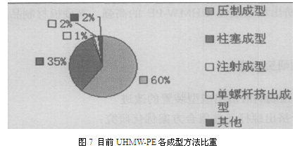
Based on the information above, we understand that UHMW-PE is characterized by its excellent performance but also by its difficulty in processing. Conventional polymer processing methods are not suitable for molding UHMW-PE products, which has limited the widespread use of UHMW-PE for some time. Therefore, research on the molding and processing of UHMW-PE is particularly important. Commonly used molding methods include compression molding (around 1965), extrusion molding (around 1970), and injection molding (around 1975). Among them, compression molding is the most widely used, accounting for approximately 60% of the total molding volume. In recent years, with the continuous development of technology, the application of extrusion molding has increased, accounting for about 35% of the total molding volume. Injection molding, on the other hand, is a relatively new molding method for UHMW-PE and is not yet widely used, accounting for approximately 5% of the total molding volume [9]. Figure 7 shows the current proportion of each molding method for UHMW-PE. Additionally, several special molding methods have been developed in recent years. Here is a brief introduction to various molding methods for UHMW-PE:
2.5.1 Compression Molding
(l) Compression-Sintering Method
Among the processing methods for UHMW-PE, the compression-sintering method is currently the most widely used and primitive approach. It involves loading the mold with material, applying pressure, and then placing the mold and material together in a heating furnace for heating and plasticization. Afterward, the mold is removed for cooling, and finally, the product is extracted. The key factors in this molding process are controlling pressure, sintering temperature, and time. Insufficient pressure can result in a loose texture and poor physical and mechanical properties of the product, while excessive pressure can lead to unnecessary power consumption. The sintering temperature and time should be selected based on the specific product, with the ideal outcome being a transparent product. If the sintering time is too short or the temperature too low, the product may not be fully plasticized, resulting in a white core. Conversely, excessive temperature or time can cause discoloration and degradation.
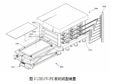
A Korean patent [10] introduces a device for producing UHMW-PE sheets, as shown in Figure 8. It mainly consists of a mold (100), a transfer table (200), a compression molding machine (300), a mold transfer unit (400), and a compression molding plate heating unit (500). The height of the mold support surface on the transfer table is adjustable. The compression molding machine comprises a movable frame (310), a fixed frame, compression molding plates (331~334), and a compression unit. The compression molding plates move reciprocally between the fixed and movable frames. The compression molding plates heat the mold. The compression unit presses down on the compression molding plates from one side, and then the UHMW-PE material in the mold undergoes compression molding, ultimately producing a UHMW-PE compression sheet. This device enables automated production, thereby reducing production cycles.
(2) Free Sintering Method
The Free Sintering Method, also known as Compression-Sintering-Compression Method, involves placing UHMW-PE powder into a mold at room temperature and compressing it under high pressure to form a blank. The blank is then heated in an inert gas-protected furnace and removed after a period of heating. Finally, it is placed in another pressing mold for pressurized cooling, and the product is released after depressurization.
(3) High-Speed Compression Molding Method
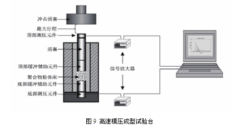
Jauffrès et al. [11] employed the High-Velocity Compaction method for molding UHMW-PE, as illustrated in Figure 9. This method involves applying high-speed impact to a mold filled with powder at a temperature close to the polymer's melting point to form a blank, which is then sintered into shape. Repeated impacts cause local melting at the particle interfaces, and during the cooling process, the recrystallization of the melted material forces the particles to fuse. This method is suitable for processing semi-crystalline polymers without viscosity restrictions, making it particularly suitable for molding UHMW-PE. Compared to conventional molding methods, this approach not only significantly reduces molding time but also enhances the tensile modulus and yield strength of the product, improving its plasticity. This method is ideal for mass production of small to medium-sized products [12].
2.5.2 Extrusion Molding
(l) Single-Screw Extrusion Molding
The world's earliest developer of UHMW-PE single-screw extrusion molding technology was Japan's Mitsui Petrochemical Company. They began researching UHMW-PE rod extrusion technology in 1971 and put it into production in 1974, using a modified φ65 mm single-screw extruder. Due to the high viscosity of UHMW-PE, it remains viscoelastic in its molten state with almost no fluidity, and the friction coefficient between the material and the barrel is small. As a result, the material is difficult to transport forward. When using conventional barrels and screws, the material often wraps around the screw and cannot be transported forward.
The Institute of Plastic Machinery and Plastic Engineering at Beijing University of Chemical Technology has been studying UHMW-PE extrusion processing technology since 1993 and has achieved continuous extrusion of UHMW-PE pipes using a single-screw extruder. A special single-screw extruder is used, featuring a combined barrel and a large-thrust screw. The barrel consists of a grooved section and a smooth section to prevent material slippage, while the latter allows for greater propelling force and plasticizing capability, overcoming the melt resistance caused by high viscosity. However, if the process technology, extruder, and mold are not well-matched, a complete pipe billet cannot be produced. In recent years, through continuous research and development, the institute has achieved direct extrusion of UHMW-PE profiles, rods, and pipe products with a viscosity-average molecular weight of over 3 to 10 million without adding any additives [13].
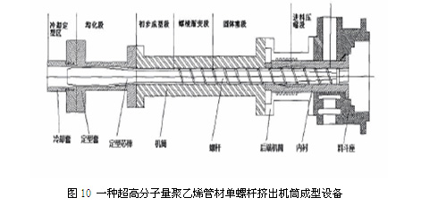
Qin Jianhua et al. [14] invented a single-screw extruder barrel molding equipment for UHMW-PE pipes, as shown in Figure 10. This equipment takes advantage of the extrudable and calenderable properties of UHMW-PE in its high elastic state. Under a certain extrusion force, the UHMW-PE in its high elastic state fills the cavity formed by the screw and the barrel, achieving preliminary molding. With continued extrusion force, the preliminarily molded pipe achieves temperature and geometric uniformity through a shaping core rod and shaping sleeve, and then rapidly completes the cooling and shaping process through a cooling sleeve.
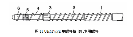
A US patent [15] introduces a special screw for a UHMW-PE single-screw extruder, as shown in Figure 11. The screw consists of three sections: the feeding section (1,2), the transition section (3,4), and the metering section (5,6). The feeding section is further divided into two parts: the conveying section (1) and the decompression section (2). The transition section includes a shear element (3), and the metering section includes a mixing element (5). This screw not only ensures the stability of the processing but also prevents thermal degradation of the material.
(2) Twin-Screw Extrusion Molding
When extruding UHMW-PE with twin screws, the material can be forcibly transported forward due to the meshing of the two screws, providing axial material transportation capability. Therefore, there is no need to slot the barrel. To reduce shear between materials and ensure that the relative molecular weight of the material does not decrease, it is preferable to use a co-rotating twin-screw extruder. The screw speed should not be too high to avoid affecting the flow stability of the material and the quality of the product, as well as to prevent material degradation. Due to the poor fluidity, high viscosity, and high extrusion back pressure of the material, the gearbox should be equipped with a large thrust bearing [16].
Wang Qingzhao et al. [17] studied the production method of extruding UHMW-PE sheets using a twin-screw extruder and a fish-tail die. By employing a parallel co-rotating twin-screw extruder or a conical counter-rotating twin-screw extruder with an axial pressure resistance of over 40 MPa, and pairing it with a fish-tail die with a compression ratio of 1.5~2.0 and a cooling device, continuous production of UHMW-PE sheets and profiles can be achieved using appropriate extrusion processes.
(3) Plunger Extrusion Molding
Plunger extrusion molding, as a reciprocating intermittent extrusion method, is an early plastic processing technique. The processing procedure involves adding powder to the feeding chamber and mold, and applying high pressure through a plunger to move the compressed powder through three steps: continuous sintering, cooling, and shaping, to achieve semi-continuous extrusion molding. This method can be seen as continuous pressing-sintering, which is more efficient than compression molding. However, due to the small contact area between the raw material and the heating element, heating efficiency is low, so rapid extrusion is not possible; otherwise, the product may have an undercooked core, resulting in defective products. The advantage of this method is that there is no shear during the molding process, so the reduction in relative molecular weight is small, and the internal quality of the product is good. Additionally, this molding method is not limited by the relative molecular weight, and extrusion processing can be achieved even with a relative molecular weight of up to 10 million. This is currently one of the most commonly used methods in UHMW-PE processing and is widely used in Europe and the United States, mainly for processing bars of a certain length, as well as extruded pipes, sheets, and profiles [18].
Zhang Yufei et al. [19] developed the STJ series plunger-type extruder for UHMW-PE pipes, bars, and other products based on polytetrafluoroethylene (PTFE) plunger extrusion technology and according to the processing characteristics of UHMW-PE. The extruder adopts a vertical structure with quadruple motion, overcoming the feeding unevenness of horizontal processing equipment. It also improves material fluidity and mold filling reliability, reduces extruder resistance, and minimizes the likelihood of melt fracture, ensuring product quality. This plunger-type extruder can process UHMW-PE raw materials with a molecular weight of 1.5 to 4 million, resulting in excellent product performance. Its production efficiency greatly surpasses traditional compression sintering methods, enabling continuous and industrialized production.
Liu Guangjian et al. [20] developed a double plunger extrusion equipment, as shown in Figure 12. The equipment mainly consists of a dual hydraulic system, feeding section, heating section, buffering section, and phase difference lag device. The heating section adopts a special mechanism and structure, namely a thin plate structure, which allows for rapid heating and significantly improves production efficiency. The buffering section is the core component and can largely compensate for the deficiencies of plunger extrusion. Additionally, the use of double plungers for alternating extrusion enables continuous extrusion, minimizes pulsation, and reduces the occurrence of poor cooling in the product.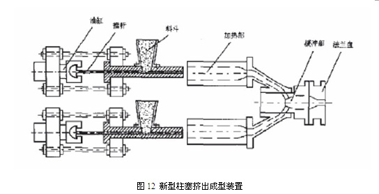
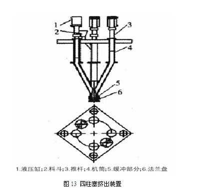
Xiong Shuyun et al. [21] developed a four-plunger UHMW-PE extrusion device based on the working principle of plunger extrusion, as shown in Figure 13. It maintains the advantages of a vertical plunger extruder, such as a small footprint, simple operation, good plunger and mold alignment without easy deviation, and high precision of the produced products. With four plungers operating alternately, the extrusion process is relatively continuous, and the pulsation phenomenon on the product surface is minimized, improving the surface quality of the product.
2.5.3 Injection Molding
During injection molding of UHMW-PE with special melt characteristics, jetting often occurs, resulting in porous products or layered delamination. Therefore, UHMW-PE is difficult to injection mold [22]. Japan's Mitsui Petrochemical Company first achieved UHMW-PE injection molding in the mid-1970s and commercialized it in 1976; Germany and the United States subsequently achieved UHMW-PE injection molding as well.
In China, there are also researchers studying the injection molding of UHMW-PE. Liu Yufeng et al. [23] studied the injection molding process of UHMW-PE using a high-pressure and high-speed injection molding machine from Battenfeld, a German company. The results showed that due to the extremely high melt viscosity of UHMW-PE, which is less affected by temperature, increasing the barrel temperature has little effect on improving melt flow performance. Increasing the injection pressure can significantly improve the fluidity of the resin. However, if the injection pressure is too high, it can cause material overflow. The injection speed is selected to increase first and then decrease. Under high shear, the melt is divided into fine powders, filling the cavity. Meanwhile, choosing a smaller diameter nozzle to increase shear, coupled with an appropriate screw speed, can produce products with excellent performance. The disadvantage of using a high-pressure and high-speed injection molding process is that the equipment has low power, and there is an increased risk of resin oxidation and molecular chain breakage degradation under high shear [24].
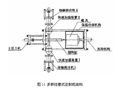
Sun Lihong [25] studied the injection molding of large UHMW-PE parts and developed a special UHMW-PE injection molding machine based on a plunger-type UHMW-PE extruder, as shown in Figure 14. This injection molding machine can achieve the molding of large UHMW-PE parts weighing 2 to 20 kg, maximizing the performance indicators of UHMW-PE. At the same time, production efficiency can be increased to 6 to 7 times the original, and the utilization rate of raw materials has increased from about 55% to 80% to 90%, reducing the processing cost of parts and replacing the current sintering-compression molding method used for processing large UHMW-PE parts.
2.5.4 Blow Molding
UHMW-PE is used in blow molding, and its products have excellent impact resistance, mainly applied to large blow-molded products. The most important characteristic of resins for large blow-molded products is their sag resistance. The sagging of parisons severely affects the quality of the product. Due to the large molecular weight of UHMW-PE, its melt has excellent viscoelasticity. When the material is extruded from the die, it exhibits a certain "melt stiffness" due to elastic recovery, resulting in strong sag resistance [26]. UHMW-PE blow molding can also produce high-performance films with balanced strength in both vertical and horizontal directions, thus solving the long-standing problem of inconsistent strength in the vertical and horizontal directions of high-density polyethylene films, which can easily cause transverse damage to the films.
In 2005, Mitsui Oil Chemical in Japan introduced a new processing method for UHMW-PE blow molds. It produces biaxially oriented blow-molded films by combining compression molding and blow film extrusion. The resin powder in the barrel is tightly compressed by a single-screw extruder with shallow threads, groove surface mechanism, and a screw length-to-diameter ratio exceeding 30:1, until the powder particle interface disappears. Then, the hot viscoelastic solid material enters a rotating right-angle head with a threaded bottom, so that the melt forms a tube over a rotating core mold heater. The rotating core heater overcomes many disadvantages in extrusion, allowing the tubular melt to be blown into a non-ruptured film. Using this method to blow mold UHMW-PE, the maximum load stretch ratio is 6:1 to 30:1, the blow-up ratio is 6:1 to 10:1, and the film thickness is 5 to 140 micrometers [27].
2.5.5 Special Molding and Processing Techniques
(l) Gel Spinning
Gel spinning is a novel spinning technique that requires polymers with a high average molecular weight and a reasonable molecular weight distribution, which UHMW-PE meets [28]. In 1979, Dutch company DSM first applied for a patent on UHMW-PE gel spinning and achieved industrial production. Figure 15 shows the gel spinning process flowchart of DSM [29].
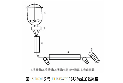
The process of producing UHMW-PE fibers using this method involves dissolving UHMWPE in a suitable solvent to create a semi-dilute solution. This solution is then extruded through a spinneret and quenched rapidly with air or water to solidify it into a gel fiber. From a macromolecular perspective, the polyethylene macromolecules in the solution are in an untangled state and maintain this state in the gel fiber. Stretching the gel fiber aligns the macromolecular chains and promotes high crystallization, transforming the folded macromolecules into straight chains, resulting in high-strength, high-modulus fibers [30]. The tensile strength of UHMW-PE fibers obtained by this method can reach up to 2.8 GPa, making them widely used in the production of bulletproof vests, safety helmets, cut-resistant gloves, climbing ropes, fishing lines, suspension cables, etc. [31].
(2) Co-lubricated Extrusion (Injection) Molding
UHMW-PE co-lubricated extrusion (injection) molding involves two scenarios. One method involves pressing a lubricant into the mold cavity through a gap, creating a lubricating layer between the inner surface of the cavity and the molten material. This technique is suitable for almost all resin materials, especially those ultra-high molecular weight substances that require molding in a highly viscous state. For instance, when producing UHMW-PE sheets, SH200 silicone oil is pumped into the mold cavity as a lubricant using a metering pump. This significantly improves the appearance of the final product, particularly increasing tensile strength due to reduced extrusion deformation. The second method is the microporous body method, where a microporous liner is created using powder metallurgy material with fine interconnected pores as part of the mold or connector. A low-viscosity liquid is then forcibly injected into the mold cavity or runner to form a lubricating layer. This technique enhances the flow properties of the melt within high-shear die orifices, reduces pressure within the mold cavity, and facilitates the removal of weld lines on the melt surface. When co-lubricated extrusion of UHMW-PE round bars is performed using the microporous body method with ethylene glycol, the internal stress of the bars is reduced, and shrinkage deformation is significantly decreased [32].
Li Yanmei et al. [33] conducted research on the twin-screw forced lubrication extrusion of UHMW-PE sheets. The results showed that continuous extrusion molding of the UHMW-PE system could be successfully achieved through forced lubrication of the die channel, a reasonable screw combination, correct process conditions, and adjustments to the die channel pressure.
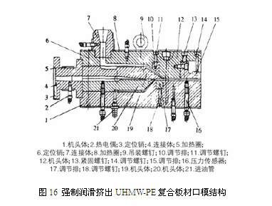
Yuan Hui et al. [34] designed a forced lubrication extrusion die for UHMW-PE composite sheets. The die head is a 3-layer composite forced lubrication extrusion die, with medium molecular weight polyethylene on the top layer, flow-modified UHMW-PE in the middle layer, and heat-resistant silicone oil on the bottom layer, as shown in Figure 16. Hot silicone oil is pumped into the bottom layer of the sheet using a pressure pump. The addition of hot silicone oil significantly reduces the shear force between the UHMW-PE layer and the die lip, transforming the flow of UHMW-PE melt into plug flow and significantly reducing the impact of shear rate on product performance.
(3) Solid-state Extrusion Molding
Solid-state extrusion molding is a crucial process for achieving self-reinforcement effects in polymer materials. It involves shaping materials below their melting temperature. By enhancing the size and distribution of the reinforcing phase, the aspect ratio can be significantly improved, and preferential orientation can be achieved in spatial distribution. This results in processed materials with superior specific stiffness, specific strength, dimensional stability, good impact strength, and a lower coefficient of linear expansion, thus achieving the goal of reinforcement. Solid-state extrusion molding includes cold drawing, plunger-type solid-state extrusion, hydrostatic solid-state extrusion, and die drawing [35].
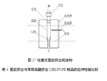
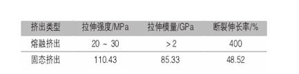
Mao Xulin et al. [36] studied the process and mechanism of solid-state extrusion molding of UHMW-PE and developed a custom plunger-type solid-state extruder, as shown in Figure 17. Plunger-type solid-state extrusion is a form of solid-state deformation. Its molding principle involves subjecting the polymer to intense tensile deformation, orientation, grain refinement, recrystallization, and microfibrillation as it passes through the die, resulting in products with higher strength and modulus. A comparison of the tensile properties of solid-state extruded and conventionally melt-extruded UHMW-PE products is shown in Table 4 [37].
Tetsuo Kanamoto et al. [38] studied a two-stage stretching method for UHMW-PE. Firstly, UHMW-PE films were prepared by compression molding and cut into strips. Then, a lower stretching ratio was achieved through solid-state co-extrusion. Finally, stretching was performed at high temperatures ranging from 120 to 135℃. After the two-stage stretching process, the stretching ratio of the films could reach 77, with a tensile modulus as high as 107 GPa. The stretching temperature and rate had a significant impact on the stretchability in the second stage and the uniformity of the final stretched films.
(4) Radio Frequency Processing and Molding
Gauvin from Canada introduced a new method for processing UHMW-PE using radio frequency: After evenly mixing UHMW-PE powder with powder additives with high dielectric loss (such as carbon black), the mixture is irradiated with radio frequency. The generated heat can soften the surface of the UHMW-PE powder, making it easier to consolidate under appropriate pressure. Using this method, large components can be molded within a few minutes [39].
(5) Gas-assisted Extrusion Technology
In traditional UHMW-PE extrusion molding, most extrusion processes between the melt and the extrusion die wall are non-slip adherent die extrusion methods. R.F. Liang et al. [40] first studied the Gas-assisted Extrusion method. The study found that when gas is injected at a lower rate into the interface between the mold and the molten material, a stable gas layer can form at the interface, providing full-slip boundary conditions on the wall. Wall boundary conditions have a significant impact on the gas-assisted extrusion molding of highly viscous viscoelastic fluids.
Zhang Xiaoxia et al. [41] studied the gas-assisted extrusion process for UHMW-PE. The results showed that the formed air film turns the shear flow of the material into plug flow, reducing the frictional resistance between the material and the extruder head flow channel. This achieves a significant viscosity and resistance reduction effect, minimizing shape differences caused by varying shear rates, resulting in an extrudate with a consistent cross-section as the die [42].
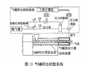
The UHMW-PE gas-assisted extrusion system mainly consists of three parts: a gas-assisted extrusion control system, a UHMW-PE dedicated extruder, and a gas-assisted extrusion die, as shown in Figure 18. UHMW-PE gas-assisted extrusion can reduce defects such as extrusion swell and melt fracture during the molding process, improving production efficiency.
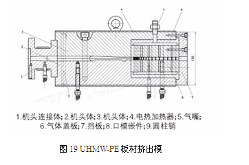
Sun Yang et al. [43] designed and developed a UHMW-PE sheet extrusion die, as shown in Figure 19, addressing the difficulty of extrusion processing for UHMW-PE. The air channels on the die insert are arranged unequally. Considering the high temperature and viscosity of UHMW-PE as it enters the die insert, the spacing between the air channels at the entrance is smaller to ensure smooth extrusion.
(6)Laser Sintering Method
Goodridge et al. [44] studied the feasibility of processing UHMW-PE products using the laser sintering method. This method enables the production of products with a multilayer composite structure.
的物料平铺到成型室中。
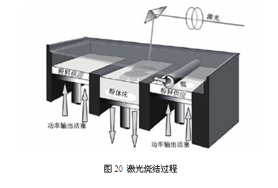
The research was conducted on a laser sintering device, as shown in Figure 20. The device consists of three chambers: the middle chamber is the molding chamber where the product is formed on a "powder bed"; the two side chambers are supply chambers. Each chamber has a platform controlled by a piston. The platforms in the supply chambers incrementally move upward to provide new powder layers, while the platform in the molding chamber decrementally moves downward, allowing the next powder layer to be stacked on top of the previously sintered layer. The role of the roller is to evenly spread the material from the supply chambers into the molding chamber.
To minimize temperature gradients during the processing, the material in the powder bed is preheated before sintering, with a temperature below the material's melting point. Then, under the action of a laser, the material is melted and sintered into a solid. The material in the supply chambers also needs to be preheated, but the preheating temperature should be lower than that of the material in the powder bed, so that less heat is required when the material is spread into the molding chamber. The main factors affecting the processing are the temperature of the supplied material, the temperature of the powder bed, the speed of the roller, and the laser energy.
3. Research on UHMW-PE Single-Screw Extrusion Molding Method
3.1 Raw Materials for Experiment
UHMW-PE: Type M-2, provided by Beijing Auxiliary Agent No. 2 Factory;
Polyethylene Wax: Molecular weight between 3000-4500, provided by Beijing Institute of Chemical Technology.
3.2 Experimental Equipment
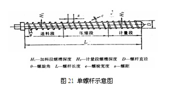
Single-screw extruder: SJ-90A, screw diameter of 90mm, screw aspect ratio L/D=25, axial pressure resistance of 30-35MPa, provided by Shanghai Extrusion Machinery Factory; a schematic diagram of the single screw is shown in Figure 21.
Mold: Compression ratio of 2.0-2.5, requiring the mold to generate a back pressure of 30-40MPa. The surface roughness Ra of the mold cavity should be below 0.4µm, preferably chrome-plated. The mold outlet is equipped with a water circulation cooling device, and the mandrel is oil-cooled.
3.2 Sample Preparation
Mix 100 parts of UHMW-PE with 5 parts of polyethylene wax and extrude the sample using the modified single-screw extruder.
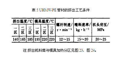
3.3 Extrusion Process Conditions
Taking the extrusion of UHMW-PE pipes with an outer diameter of 73mm and a wall thickness of 5mm as an example, the process conditions are shown in Table 5.
3.4 Modification of the Extruder
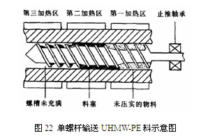
As mentioned above, UHMW-PE remains viscoelastic even in a molten state, with almost no fluidity, and the friction coefficient between the material and the screw and barrel is very small. Therefore, it is difficult to transport the material in the barrel. In other words, using a single-screw extruder to convey material solely relying on the shear between the screw and the barrel cannot push the material forward along the screw groove. This often causes the material to stagnate in the compression section of the screw and form a plug wrapped around the screw. The material in the metering section cannot fill the screw groove, resulting in feeding failure, as shown in Figure 22.
To enable the transportation of molten UHMW-PE through a single-screw extruder, we have modified the extruder based on insights from twin-screw extruders. Specifically, axial grooves, resembling rifling in a gun barrel, were cut into the inner wall of the extruder barrel, as illustrated in Figure 23. These parabolic-shaped grooves serve a dual purpose: to prevent the formation of material plugs and to facilitate the radial movement of material within the grooves, ensuring that material does not get trapped. In other words, the design eliminates dead spots, preventing UHMW-PE melt from remaining in the grooves for extended periods or permanently. The depth and width of the grooves are proportional to the barrel diameter. For a barrel with an inner diameter of 90mm, the designed groove width is 8mm, and the depth is 6mm. Ideally, the groove width should be 8%-10% of the barrel diameter, and the depth should be 5%-8% of the barrel diameter.
If the axial grooves were designed as straight lines, the material within would only experience radial forces, lacking axial propulsion. While this would prevent material plugs in the compression section, it would significantly reduce the transport efficiency as the material would not advance axially. By contrast, the rifling design subjects the material to both radial and axial forces, effectively preventing plugs and propelling the material axially, thereby greatly enhancing transport efficiency. Due to the significant difference in pitch between the rifling and the screw, the material rotates at a higher speed within the screw compared to the grooves. This creates a substantial shear force between the screw and the barrel, preventing material plugs. Much like the meshing transport mechanism of a twin-screw extruder, this design forcibly propels the material, achieving the goal of transporting the UHMW-PE melt into the mold.
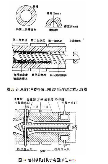
We have installed three riflings, evenly distributed at 120° intervals on the cross-section of the barrel. For barrels of various diameters commonly used, installing three riflings is reasonable, considering both effectiveness and ease of processing.
Similar to other plastics, UHMW-PE goes through three processes in the barrel: heating, plasticization, and transportation. However, the difference lies in the fact that in its molten state, the viscosity of UHMW-PE melt can reach up to 1×10⁸ Pa·s, resulting in significant resistance during transportation. This requires a high axial thrust from the screw, meaning the thrust bearing at the end of the screw must be able to withstand considerable back pressure. This back pressure consists of two components: one generated by the screw shearing the material and transporting the melt forward (this component exists even during extrusion without a mold installed), and the other resulting from overcoming the molding resistance when transporting the melt into the mold. Experimental results indicate that during the extrusion of UHMW-PE pipes with an outer diameter of 73mm and a wall thickness of 5mm, the maximum indicated value on the melt pressure sensor at the junction between the barrel and the mold can reach up to 32MPa. Therefore, when selecting a single-screw extruder for extruding UHMW-PE pipes, it is essential to choose an extruder with sufficient axial thrust based on the cross-sectional area of the pipes. Experience has shown that when producing UHMW-PE pipes, the axial thrust of the screw should be greater than the pipe cross-sectional area multiplied by 30-35 MPa.
4. Research on UHMW-PE Twin-Screw Extrusion Molding Method
As the application scope of UHMW-PE continues to expand, there is an urgent need to develop a method for continuous molding of UHMW-PE. Currently, the single-screw extrusion molding technology developed domestically and internationally offers higher production efficiency compared to press-sintering and plunger extrusion. However, due to the low friction coefficient between UHMW-PE and metal, the solid conveyance using single-screw extrusion is limited. As a result, this molding technology not only requires high equipment standards but also has a very limited production rate.
In contrast, the co-rotating twin-screw extruder can better overcome these shortcomings. The twin-screw extruder has a self-cleaning function due to the meshing of the two screws, which can forcibly propel the material and provide axial forced material transportation. Therefore, there is no need to cut grooves on the barrel, and the plasticizing and mixing effects are excellent.
4.1 UHMW-PE Twin-Screw Extruder Equipment Design
4.1.1 Die Structure and Its Characteristics
This die is a 3-layer composite forced lubrication extrusion die, with a sheet width of 160mm and a total thickness of 6mm. The upper layer is medium molecular weight polyethylene, supplied by a Ø30mm single-screw extruder. The middle layer is flow-modified UHMW-PE, extruded through a Ø34mm twin-screw extruder. The lower layer is heat-resistant silicone oil. The overall structure is shown in Figure 25. The die has the following characteristics:
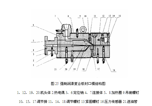
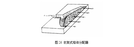
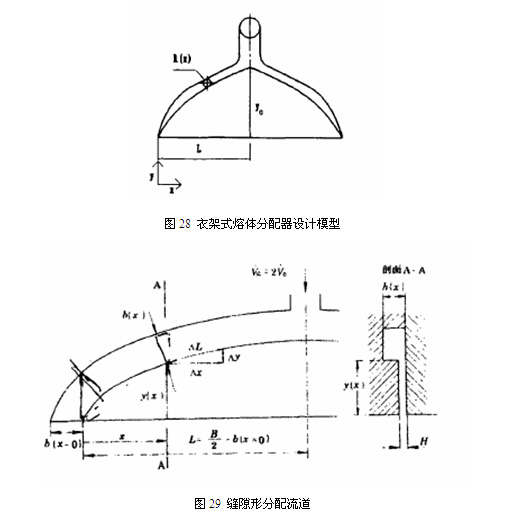
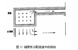
(l) It adopts a hanger-type melt distributor [46], with a flow channel shape as shown in Figure 25. It combines the advantages of both T-shaped and fish-tail shaped dies, featuring a smaller diameter and variable manifolds along the flow direction, as well as a large diffusion angle in the fan-shaped area similar to a fish-tail shaped die. This design allows for uniform melt flow across the entire die width, making it particularly suitable for wide sheet production and easy to industrialize. The upper layer adopts a slit-shaped distribution channel, which has significant advantages in rheology and manufacturing. Its flow is a combination of distribution channels and slits, as shown in Figure 26.
(2) The thickness of each layer of the composite sheet is adjustable. The die adopts fine-tuning screws to adjust the gaps between layers, controlling the thickness of the UHMW-PE layer, HDPE layer, and the total thickness of the sheet product, thus obtaining sheets of different thicknesses.
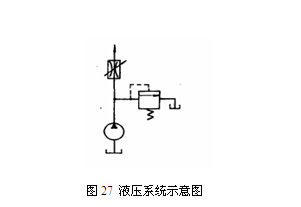
(3) It adopts forced lubrication extrusion [47], where a pressure pump is used to inject heat-resistant silicone oil into the lower layer of the sheet. The hydraulic system is shown in Figure 27. The composition of the forced lubrication hydraulic system is as follows:
Hydraulic oil: Heat-resistant methyl silicone oil, temperature resistance of 250℃, SH200
Three-phase asynchronous motor: Y100LI-4, Shanghai Anyuan Electric Motor Factory
Gear pump: CBN-F3, Jiangsu Huaiyang
Overflow valve: YF-L10HI-S type, Shanghai No. 2 Hydraulic Component Factory
Throttle valve: 200OL&J, Taiwan
The infiltration of heat-resistant silicone oil significantly reduces the shear between the UHMW-PE layer and the die lip, allowing the UHMW-PE melt to flow in a plug-like manner. This minimizes the impact of different shear rates on product performance.
(4) This die adopts electric heating, which is convenient to use and environmentally friendly.
(5) This die is connected to a twin-screw extruder to achieve efficient and continuous extrusion of UHMW-PE, thereby improving the production efficiency of UHMW-PE products.
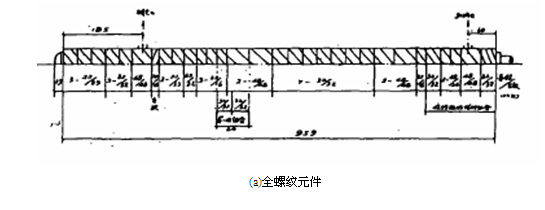
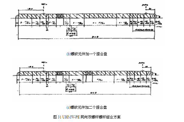
4.1.2 Determination of Screw Combination Scheme
For the special material UHMW-PE, based on its melt characteristics, three different screw combinations (as shown in Figure 31) were designed for experimentation. In the figure, (a) represents a full-thread element structure that utilizes elements with different leads to compress the material, primarily focusing on enhancing material transportation. A pair of left-handed threaded elements are combined before the exhaust port to create damping, facilitating exhaust. This combination examines the effects of screw element combinations that primarily focus on material transportation with some mixing action on the transportation, mixing, melting, and extrusion of highly viscoelastic materials. This full-thread element structure is designed specifically for the extremely high viscosity of ultra-high molecular weight polyethylene melts. To reduce the working torque of the twin-screw extruder and ensure normal machine operation, all mixing elements (kneading disks) in conventional screw combinations have been eliminated. Of course, this comes at the cost of sacrificing the mixing effect of the blend. (b) Combines a 45° kneading disk in the middle and front of the screw. Since the kneading disk has no conveying ability, material can only pass through when the pressure difference on both sides reaches a certain value. Therefore, its role is to establish pressure earlier than combination (a). Coupled with the good mixing effect of the kneading disk, it aims to improve the dispersion and distribution of fillers, making the melt more uniform. (c) Adds another kneading disk in the middle of the screw to further enhance the mixing effect of the screw.
Each screw combination, paired with a standard pelletizing die, underwent extrusion pelletizing experiments under the following experimental conditions:
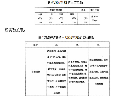
The above phenomena indicate that screw combination (a) is the best choice for the smooth extrusion of UHMW-PE.
4.2 UHMW-PE Twin-Screw Extrusion Molding Experiment
(l) Experimental formula used:
UHMW-PE/HDPE/PP/EPDM/Glass Beads (70/25/5/5/30)
(2) Experimental setup:
1. Host machine: TE-34 co-rotating twin-screw extruder from Jiangsu Keya Chemical Equipment Co., Ltd.
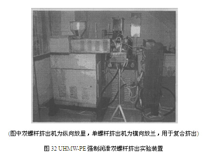
2. Die: Forced lubrication coat hanger-style sheet extrusion die, self-designed and manufactured (structure as shown in Figure 32).
(3) Experimental process flow: (See Figure 33)
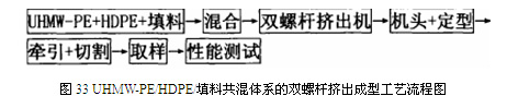
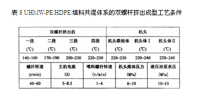
The twin-screw extrusion molding process conditions for the UHMW-PE/HDPE/filler blend system are shown in Table 8.
4. Conclusion
Ultra-high molecular weight polyethylene possesses unparalleled properties such as wear resistance, impact resistance, chemical resistance, and self-lubrication compared to other engineering plastics. It has unique advantages in various fields of the national economy, especially in wear-resistant conveyor systems, equipment lining, and various mechanical components. The development and application of its products have broad prospects and are increasingly gaining attention. The continuous emergence of high-efficiency processing technologies will further promote the development and application of UHMW-PE.